 ar
ar bg
bg hr
hr cs
cs da
da nl
nl fi
fi fr
fr de
de el
el hi
hi it
it ko
ko no
no pl
pl pt
pt ro
ro ru
ru es
es sv
sv tl
tl iw
iw id
id lv
lv lt
lt sr
sr sk
sk sl
sl uk
uk vi
vi et
et hu
hu th
th tr
tr fa
fa ms
ms hy
hy ka
ka ur
ur bn
bn mn
mn ta
ta kk
kk uz
uz ku
ku
load cell calibration
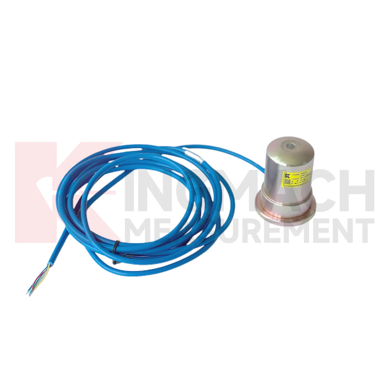
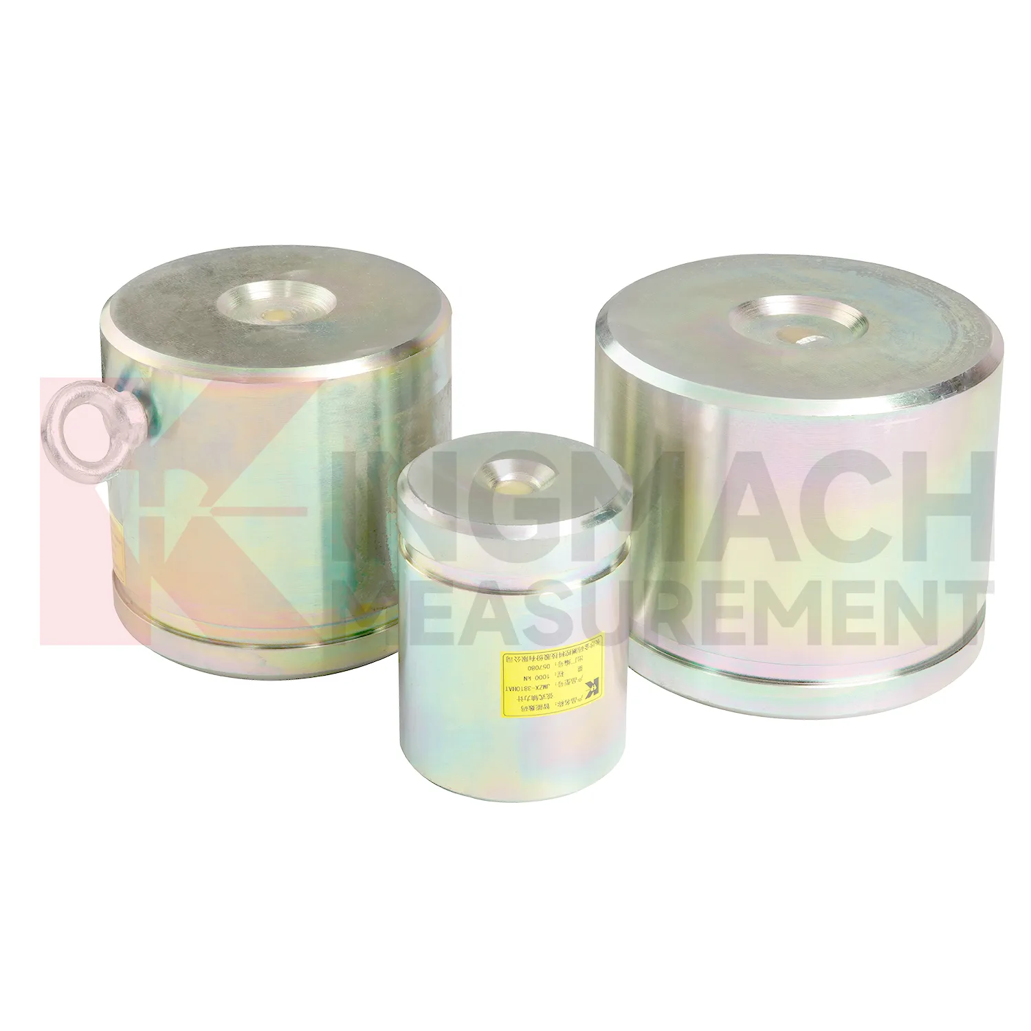
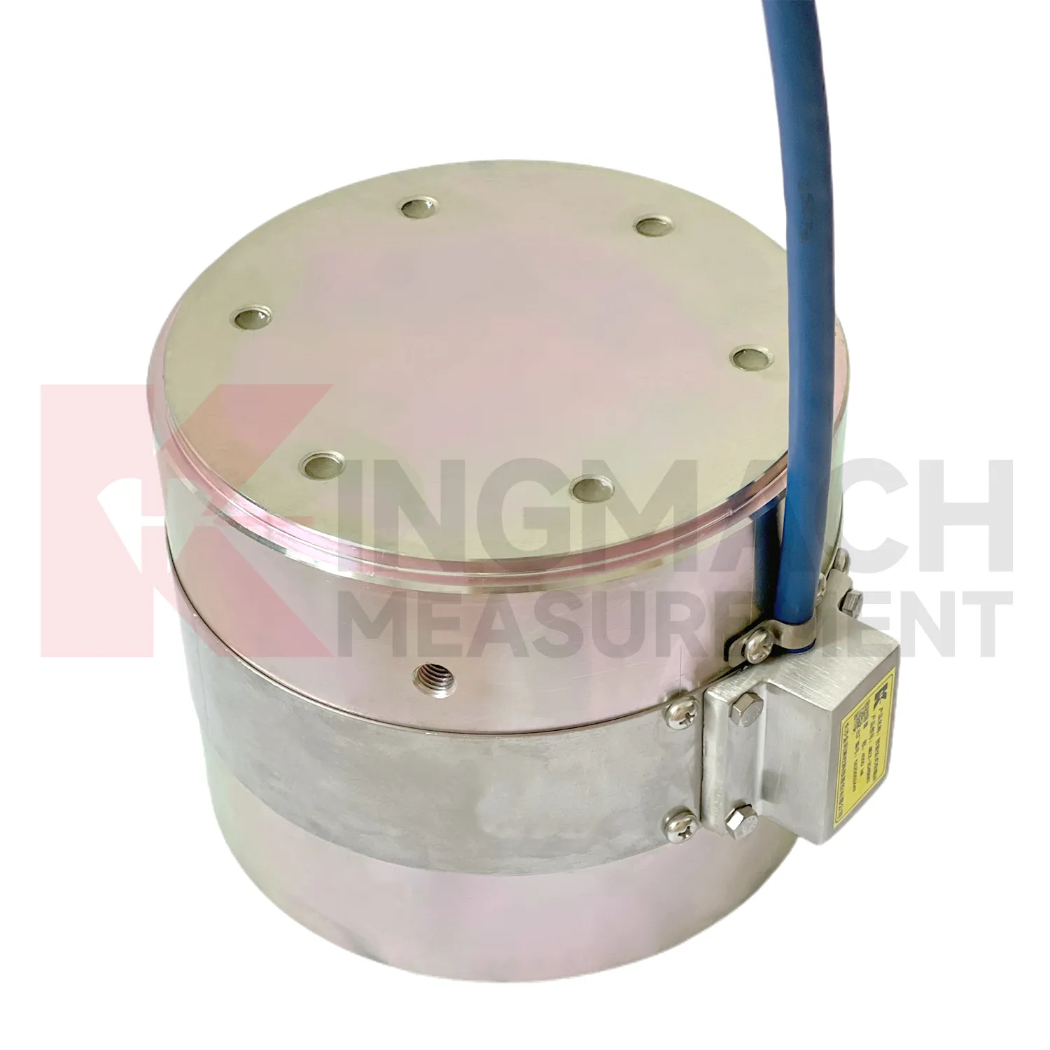
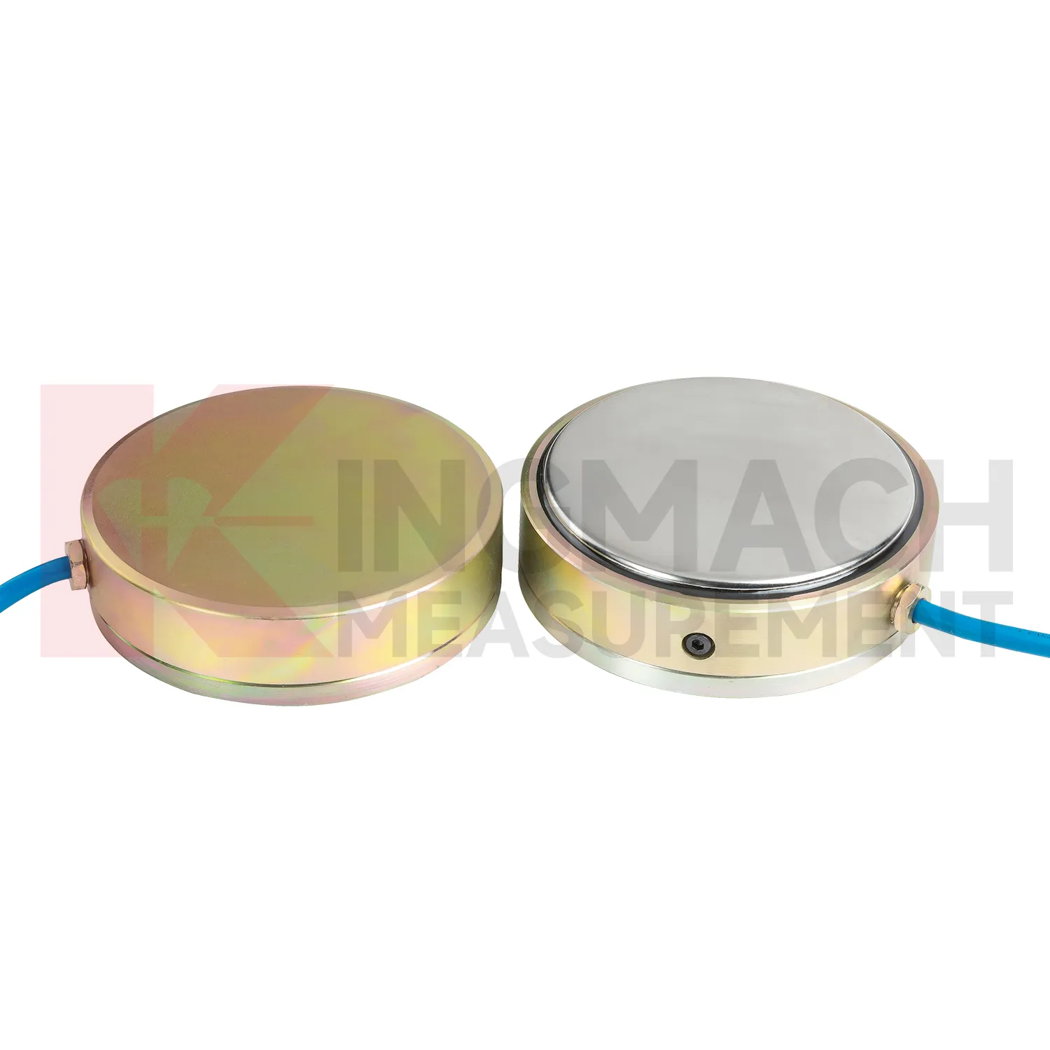
Kingmach load cell calibration products give engineers several ways to measure load depending on the contact condition. Hollow load cells fit cable and anchor force work, solid load cells fit compression and bearing capacity checks, axial force meters fit steel support monitoring, and earth pressure cells fit soil or contact pressure measurement. The listed technical span is broad: 500 kN to 8000 kN for hollow models, 1000 kN to 10000 kN for solid models, 200 kN to 3000 kN for axial force meters, and 0.3 MPa to 8 MPa for earth pressure cells. Accuracy and resolution are also stated in the product files, including 0.5%FS precision on main force models and 0.001 MPa resolution for pressure cells. Kingmach adds practical field features such as waterproofing, temperature correction, memory storage, digital output, and compatible readout instruments. A good specification compares these numbers with the design load, possible overload, installation surface, service environment, and planned inspection interval. This brand context fits projects that combine several monitoring categories rather than one isolated load point. A bridge or foundation pit may require force, settlement, displacement, water pressure, and software records in the same maintenance file, so compatibility should be reviewed early. The data record should also state whether the pressure or force point will be checked manually, automatically, or by both methods during handover.
Application of load cell calibration
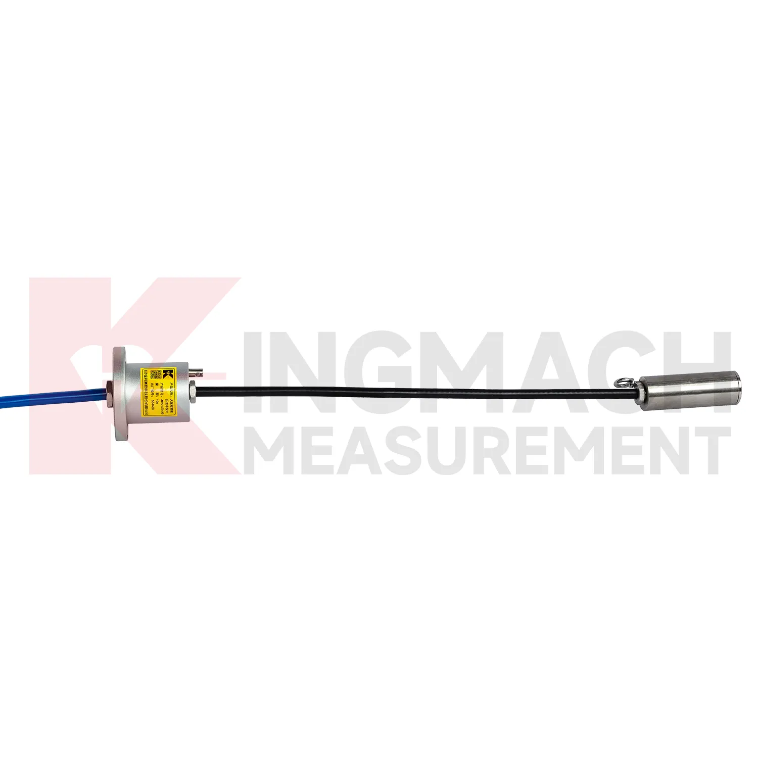
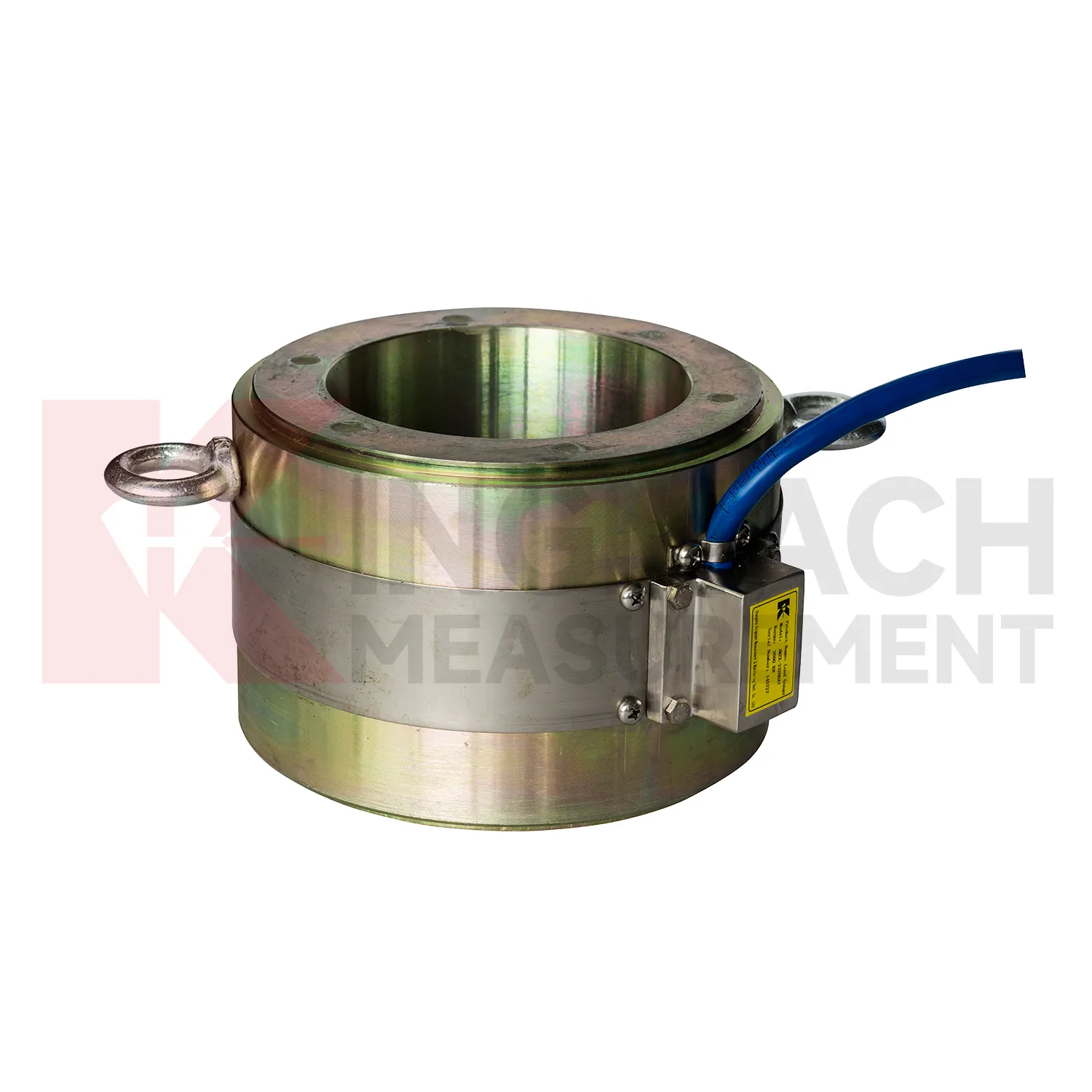
In bridge monitoring, load cell calibration can be used at cable anchor heads, stay cable force points, pier supports, bearing test positions, and pile load test setups. The pain point is simple: a bridge can redistribute force before visible cracks or displacement appear. Hollow load cells such as the JMZX-3XXXHAT cover 500 kN to 8000 kN and are built around an annular multi-string structure with temperature correction and waterproof durability. Solid load cells reach 10000 kN with 0.5%FS precision, which suits high capacity compression points and bearing capacity checks. During construction, readings can confirm prestressing, lock-off behavior, and support load transfer. During operation, the same point can be reviewed after heavy traffic, temperature swings, maintenance work, or extreme weather. Force data becomes more meaningful when compared with displacement transducers, settlement points, tiltmeters, and visual inspection results. For long span bridges, a load trend that drifts slowly can be more important than a single high reading, because it may reveal relaxation, seating loss, or uneven force sharing. Cable exit direction, waterproof joint location, inspection access, and whether the point will be buried or exposed should be decided before installation. Those details are easy to ignore in drawings, but they often decide whether a field crew can verify the reading later without disturbing the structure.
The future of load cell calibration
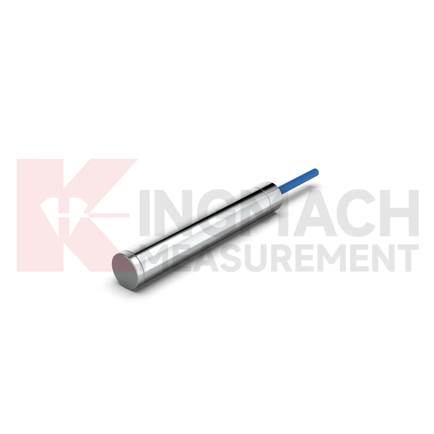
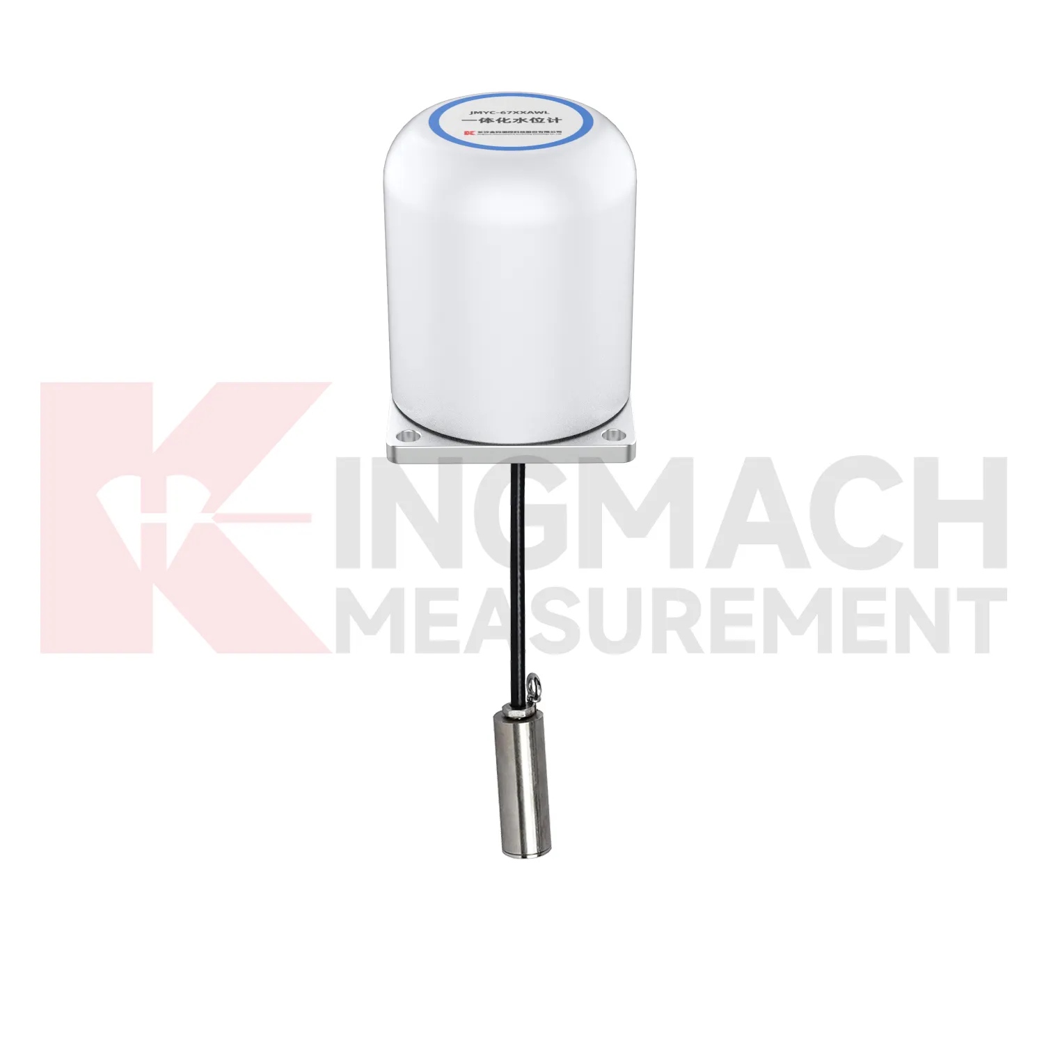
In tunnels and foundation pits, future load cell calibration use will move toward faster construction stage feedback. Axial force meters with 200 kN to 3000 kN ranges, 0.5%FS accuracy, direct kN display, and 1 MPa waterproofing already suit support load monitoring. The next step is pairing those readings with excavation depth, support installation time, groundwater level, wall displacement, and site progress records. LoRa or 4G gateways can reduce manual rounds where access is unsafe or work is moving too fast. Edge devices can flag missing channels, abnormal drift, or readings that changed after a cable was disturbed. This is different from a vague smart site label. It is a specific workflow where the sensor reading is checked against the work stage that should have caused it. As urban underground projects face stricter monitoring requirements, instruments that combine rugged installation, direct force output, and platform access will fit the way contractors actually manage risk.
Care & Maintenance of load cell calibration
For load cell calibration used with manual readouts, care depends on repeatable procedure. Before installation, store the calibration sheet with the instrument and confirm that the readout supports the sensor type. Kingmach product pages mention compatible readouts and comprehensive vibrating wire instruments, which can display force values directly on selected models. During installation, label the cable and channel clearly, record the zero value, and protect the connection point from water and pulling. During each reading round, use the same unit, readout setting, point name, and observation sequence. Note temperature, weather, construction activity, and any visible damage near the sensor. Long term maintenance should include connector cleaning, cable jacket inspection, comparison with nearby points, and periodic calibration planning according to project requirements. If a reading seems wrong, repeat it after checking the cable and readout battery. Many apparent sensor faults come from swapped channels, loose connectors, or missing zero records. Use the same readout settings.
Kingmach load cell calibration
load cell calibration can be treated as a field witness for hidden force transfer in civil structures. Concrete, steel, soil, cable systems, and hydraulic loading may all look calm while the internal load path changes. Kingmach products in this category cover hollow load cells for anchors and cables, solid load cells for compression and pile testing, axial force meters for steel support loads, and earth pressure cells for contact pressure. Each type answers a different site question. Has the anchor lost tension? Is a pile test load centered? Is an excavation support taking more force after the next soil layer is removed? Is water pressure pushing the retaining structure harder after rain? The strongest monitoring records combine the sensor model, calibrated coefficient, zero value, temperature, reading time, and construction stage. That record gives owners a way to compare today with last week, last season, or the previous loading step, instead of relying on a single inspection note.
FAQ
Q: How should load cell calibration be selected for a bridge cable or anchor point? A: Start with expected force, lock-off load, possible overload, bearing geometry, and access for later inspection. Hollow load cells are commonly used where the anchor or cable passes through the center opening. Q: What range information is available from Kingmach hollow models? A: The JMZX-3XXXHAT series is listed from 500 kN to 8000 kN, with 0.1 kN sensitivity on the 500 kN model and 1 kN on larger listed models. Q: Why does temperature correction matter? A: Cable and anchor readings can move with temperature, so built-in temperature measurement helps reduce false interpretation. Q: Can readings be stored inside the sensor? A: Smart hollow models list storage for 800 measurement records, including time, temperature, zero values, and correction data. Q: What should be checked after installation? A: Check seating, cable protection, connector sealing, zero value, first stable force, and matching channel name.
Reviews
Ryan Lewis
Fast delivery and excellent product quality. The accelerometers and tiltmeters are highly reliable. Strongly recommend this company.
James Thompson
The tiltmeters and accelerometers are very sensitive and provide precise data. Perfect for our structural health monitoring system.
Latest Inquiries
To protect the privacy of our buyers, only public service email domains like Gmail, Yahoo, and MSN will be displayed. Additionally, only a limited portion of the inquiry content will be shown.
Isabella***@gmail.comGermany
Hello, we are evaluating weir flow meters for a water management project. Please share accuracy deta...
Olivia***@gmail.comUnited States
Hello, we are currently sourcing high-precision strain gauges and load cells for a bridge monitoring...
Related product categories
- calibration of load cell theory
- load cell failure
- load cell technology
- strain gauge load cell wiring
- diagram 4 wire load cell wire connection
- load cell accuracy calculation
- load cell amplifier circuit
- load cell calibration procedure
- load cell excitation voltage
- load cell unit of measurement
- mounting load cells
- strain gauge with load cell